WB85-8520-DSF3FC
This frame uses Eachine's DSF3 EVO BRUSHED flight controller which provides an integrated DSM2/DSMX receiver. The flight controller board comes without preassembled plugs for the brushed motors, which offers the opportunity to install "the right connectors" directly form the beginning. This is noteworthy because typically JST SH1.0 plugs are installed on many flight controller boards, but powerful motors are mostly sold with Micro-JST-1.25mm plugs (compatible with Molex PicoBlade™ series connectors) only. Fortunately the component holes on the flight controller board are made such that suitable Molex plugs can be installed easily. These more professional plugs prove for a very rigid mechanical connection between plug and PCB. In summary the following components are used in this build:
- 3D-printable frame with camera mount (https://goo.gl/uGbKgy)
- 47mm tri-blade propellers (https://goo.gl/GIx5Sa)
- DSF3 EVO BRUSHED flight controller board (https://goo.gl/tpb258)
- Molex Wire-to-Board Header (part number 53047-0210), 4 pieces
- Powerful 17kV brushed motors (https://goo.gl/iPp654)
- VTX01 video transmitter with IPEX antenna (https://goo.gl/t89uNd)
- Two screws of type STP380180060S (available here: https://goo.gl/FAhjrV, other screw types may work as well)
- Suitable TPU rubber band for the LiPo battery
- Some wires, soldering skills and a bit of technical workmanship
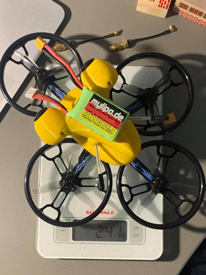
This micro quad is typically operated with 600mAh 1S LiPo batteries with 30C/60C current rating. Also 750mAh or 850mAh batteries are possible to fly with. In this example build a 25mW VTX01 video transmitter is used, however the camera mount is made to be structurally compatible with VTX02 and VTX03 video transmitters as well.

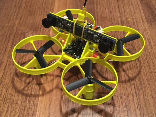
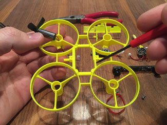
Overview of all components. Frame and camera mount are printed with ABS filament in 0.2mm standard layer thickness and two shells.

Carefully press the propellers on the motors (marking "A" for CW motors with red/blue wires and marking "B" for CCW motors with black/white wires).
Notice the notch on the inner structure of the frame. This space will be allocated later by the Molex plugs.

Carefully press the motors into the frame by slightly rotating them back and forth with help of a flat nose plier.

Motor in position. Motor housing base sits on protective post, wires are guided to left and right hand side around the post.

Install all other motors in the same manner. Take care of correct CW/CCW motor position.

Flight controller board with installed Molex plugs on PCB bottom side. Two of the four plugs will have an excess over the PCB boundary.

Bottom side view of the flight controller board. Due to mysterious design decisions the pin assignment on the PCB for + and - of each motor are not in a cyclic manner. This leads to the situation that two of the plugs will have an excess over the PCB boundary.

Put the flight controller into the bay on the frame. Now the necessity for the notch on the right hand side becomes clear.

Carefully fasten both screws. This will attach the camera mount to the frame and will fix the flight controller in its final position. There are two dedicated guide holes available for easy access to the screws.

The flight controller is pressed down and held back in its position by the four "noses" of the camera holder.

Attach all motors with the flight control board and install the elastic rubber band which will later hold the battery in place.

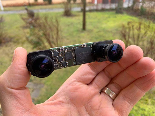
Attach 3D-camera/video transmitter module to the camera holder and guide second rubber band around as depicted here.

Wrap rubber band as shown here around the protective post on the top section of the camera mount.

This is how the camera and the video transmitter are fixed on the camera mount. Add additional silicone rings near the lenses of the camera for further mechanical stability.
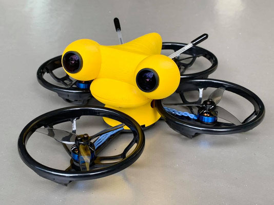
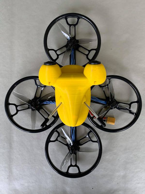
Finally done! This is how your micro quad will look like when completely assembled. Enjoy flying with it. If interested share your experiences with this frame in our discussion group on Facebook (https://www.facebook.com/groups/1390185101107008/).