WB80-8520-QX70FC
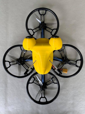
This frame is designed to mitigate a number of shortcomings of Eachine's Turbine QX70 micro quad (https://goo.gl/2sRvdS). The overall flight performance of that micro-quad is disappointing, in particular when trying to make it work together with the NanoCam3D. However, the flight controller board is not too bad and the brushed motors are OK. The customized and 3D-printable frame was made for obstruction-free 3D-vision together with a 10° camera tilt angle, resulting in a wheel base of 80mm. The following components are utilized in this build:
- 3D-printable frame with camera mount (https://goo.gl/jbBpRj)
- 47mm tri-blade propellers (https://goo.gl/GIx5Sa)
- QX70 flight controller board (also available here: https://goo.gl/M4y4CI)
- QX70 motors with SH1.0 plug (also available here: https://goo.gl/ttHFFg)
- VTX03 video transmitter with IPEX antenna (https://goo.gl/56GgwR)
- two screws of type STP380180060S (available here: https://goo.gl/FAhjrV, other screw types may work as well)
- suitable TPU rubber band for the LiPo battery
- some wires, soldering skills and a bit of technical workmanship
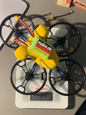
This micro quad is typically operated with 600mAh 1S LiPo batteries. The original QX70 battery works in principle, but other more powerful batteries (e.g. with 30C/60C current rating) are recommended.

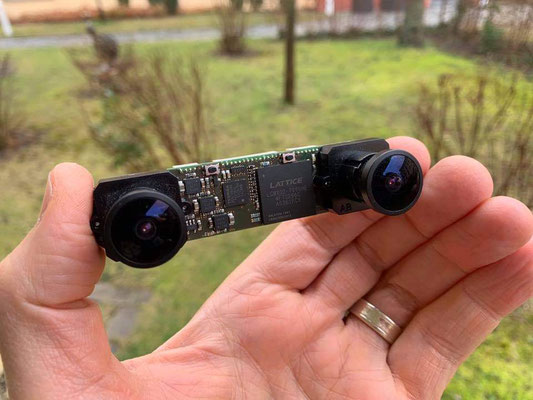
Overview of all components. Frame and camera mount are printed with ABS filament in 0.2mm standard layer thickness and two shells.

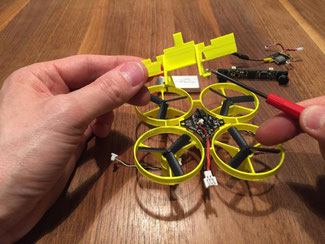
Carefully press the motors into the frame by slightly rotating them back and forth with help of a flat nose plier.

Align the motors like shown in this photo before pressing to end position. Otherwise motor wires may be damaged.

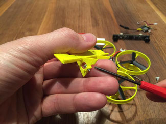
Motor in end position. Motor housing base sits on protective post, wires are guided to left and right hand side around the post.

Attach all other motors to the frame in the same manner. Take care of correct CW/CCW motor position.
Put flight controller board on its designated position in the middle of the frame and prepare mounting screws with the camera holder.
Notice the small notch on the right leg of the camera mount. This notch is necessary to not damage an exposed IC on the flight controller.

Carefully fasten both screws. This will attach the camera mount to the frame and will fix the flight controller in its final position. There are two dedicated guide holes available for easy access to the screws.

Close-up of the mentioned exposed IC which requires the notch in the camera mount.

Attach all motors with the flight control board using the SH1.0 plugs.

Put the TPU rubber band in place. There are two dedicated posts on left and right side of the frame around which the rubber band can be placed.

Correctly positioned rubber band.
The following set of photos show some details on how to connect video transmitter and 3D-camera to the power supply of the flight controller. Unfortunately the supplied wire harness of the VTX03 video transmitter cannot be used as it is. General guidelines:
- Don't supply the camera with the VTX03 5V power supply output.
- Connect the camera's power supply port in parallel to the power supply of the video transmitter.
- Modify the video input plug of the transmitter such that it fits to the plug on the camera.


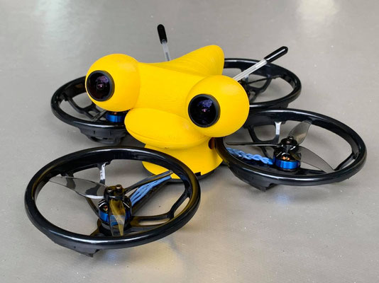
Finally done! This is how your micro quad will look like when completely assembled. Enjoy flying with it. If interested share your experiences with this frame in our discussion group on Facebook (https://www.facebook.com/groups/1390185101107008/).