
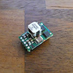
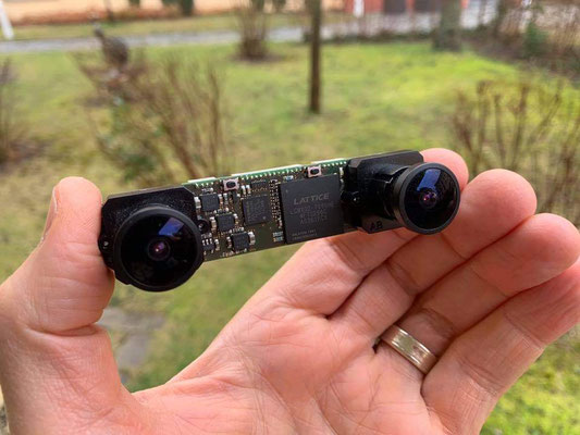
The NerdCam3D can be a diva with respect to power supply - you might have made this experience already. Therefore I would like to show you in this post how to create a tiny, lightweight and dependable DCDC converter for the camera using a commercially available converter module - the LDO03C-005W05. This device is a new high density, open frame, non-isolated converter for space sensitive applications. It has a size of only 15.5mm x 9.4mm x 8mm and a weight of 1.7g. The module features a wide input range of 3-13.8 V and offers a 0.59-5.1 V adjustable output with 3 A capability. You can use it for both step-up/step-down operation, the typical efficiency is about 90%. In summary an ideal candidate for feeding the diva.
Datasheet: http://www.artesyn.com/power/assets/ldo03c_ds_03-21-14_34aacae4a6.pdf
Technical reference: http://www.artesyn.com/power/assets/lf_ldo03_1298948396_techref.pdf
Application note: http://www.artesyn.com/power/assets/an_ldo03c_ldo06c_ldo10c_1298442035_appnote.pdf
The following description refers to the LDO03C-005W05-SJ (Mouser Part #: 826-LDO03C-005W05-SJ, Digikey Part #: 454-1279-1-ND) with horizontal SMT mounting option (see next two photos).

Step 1 - Prepare the SMT pins

Bend the 5 pins carefully outwards in order to get more space for soldering the wires and the voltage-setting resistor. The pin assigment with respect to this viewing angle on the device is:
- Pin 1 (left): enable
- Pin 2: Vin
- Pin 3 (middle): Ground
- Pin 4: Vout
- Pin5 (right): trim
Step 2 - Prepare the wire

Prepare a twin core wire and cut it to an appropriate length that fits your needs. For the following steps we define the white wire as Ground and the red wire as Power.
Step 3 - Cut and strip

Cut and strip the power wire as shown in the photo. Strip the ground wire as well, but do not cut it!
Step 4 - Tin plating

Tin-plate the bare parts of the wires. It is a good idea to twist the twin core wire as shown in the photo before tin-plating. In the next step we want to have the two red wires on opposite sides of the white ground wire.
Step 5 - Attach power wires

Attach the two red power wires to the 2nd and 4th pin as shown in the photo. Do not attach the white ground wire yet!
Step 6 - Prepare 270 Ohm resistor

Get a 270 Ohm 1% 1/8W resistor, tightly bend the leads and cut them to about 5mm. This resistor will program the converter to 5V. If you want to generate other voltages you might want to see the formula for the resistor value in the converter's application note on page 8.
Step 7 - Attach first lead of resistor

Attach the resistor at the upper pin of the DCDC converter. After that bend the resistor such that the second lead is in optimal position for being jointly soldered with the white ground wire at the converter's middle pin.
Step 8 - Attach ground wire and second lead of resistor

Finally attach the second lead of the resistor with the tin-plated bare section of the white ground wire to the middle pin of the DCDC converter. Please note that the bottom pin (ENABLE) remains unused here.
Power input 3-13.8V is on left side, power output 5V is on right side, with respect to this photo.
Step 9 - Protect the converter with thermoretractable sleeve

Finally use several sleeve sections with different diameters to achieve a complete isolation of the converter. Attach plugs or jacks at both ends of the two core wire and you're done.
Please feel free to comment on this step-by-step guide and to share your experiences with the converter.


Write a comment
Rob Gaunt (Monday, 01 August 2016 08:26)
Note for anybody reading this: The ldo-03c cannot be used as a step-up converter.
After reading this article, I bought one, hoping to step up a li-ion battery to 5v. However, it didn't work. I contacted the manufacturer (Artesyn) via email to clarify, and they answered:
"The LDO03C is implemented using a voltage-mode single phase Buck topology. So it can’t act as a step-up converter."
Otherwise, nice guide.
Rob