
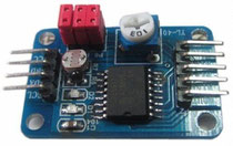
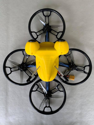
Do you want to enjoy the 3D-OSD feature with your NerdCam3D but are unable to find the necessary ADC4OSD extension board? Here comes the relief - you can simply build it on your own using a small and inexpensive COTS device called "PCF8591 AD/DA Converter Module". Although it is not so small and handy like the original ADC4OSD it fits exactly the same purpose. The converter module is available at many places under that name, for example here, or here, or here. There may be also never versions of it - this short description only refers to the version depicted here on the left side.
As already described in the instruction manual of the NerdCam3D the wiring of the converter module is simple and requires only a few resistors. You might even use it without the optional Flytron current sensors - in that case the current consumption display simply remains at 0A, but the more important information on battery voltage and flight time is visible. The most simple version of the wiring (for voltage and wall clock display only) is shown below.

The four wires on the left side are power supply (VCC and GND) as well as the I2C interface (SCL and SDA) to the NerdCam3D. These wires will be connected to the camera's extension port. Please double-check the wire sequence, unfortunately it's not identical on both sides. On the right side there are the four ADC inputs of which only one will be used. The DAC output is also not used.

This is a close-up of the top-side of the board. Notice the removed jumpers. Either remove only those two jumpers or simply remove all of them. They are only necessary when using the additional on-board components (potentiometer, light sensor, etc.) but would disturb the operation for OSD purposes. The LiPo voltage sense input (up to 6s by the way) is input AIN0. Notice the 22k series resistor in the wire from/to LiPo. Ignore the second green wire on the right side connecting to AIN1. The reason why I left the 3rd jumper in place was simply because I wanted to input the voltage from the potentiometer to AIN2 - for debugging the camera firmware.

This is a close-up of the back side of the board. Notice the 3.3K resistor from input AIN0 to GND. You can use any ground access point you want, in this case I simply used the GND pin of the (otherwise useless) potentiometer.

This is the simplified schematic of the complete wiring. You see - it's not that complicated and you don't need to be a soldering and engineering expert to succeed. The basic idea of this circuit is simply to divide the raw input voltage in such a way that a value of 25.5V is reduced to 3.3V - the maximum input voltage of the ADC. Using this voltage divider you can measure any DC voltage ranging from 0V to 25.5V with an accuracy of about +/- 0.1V.
CAUTION: Never ever connect the raw LiPo voltage without this voltage divider to the input of the PCF8591 AD/DA Converter Module. This will destroy the converter module and may damage the NerdCam3D as well.


Write a comment